Save big on select connectors!
How to Choose D-sub Connectors?
D-sub Connector Selection Guide
William Li
10/8/20251 min read
D-sub Connector Selection Guide
Step 1: Determine the Number of Cores and Layout
How many signals are needed? Standard density: 9, 15, 25, 37, 50; High density: 15, 26, 44, 62, 78
If space is limited but the core count is high → Choose the high-density series
Step 2: Select installation and termination type
Cable termination: Solder cup, Crimp, IDC piercing, PCB soldering
Equipment termination: Right angle or vertical pins
Panel mounting: Front/rear mounting, flange size (standard/compact)
Step 3: Consider environmental protection level
Ordinary indoor dry environment → Plastic shell or standard metal shell
Damp, dusty, outdoor → Waterproof series (IP67/IP68), with sealing ring and locking screws
Strong electromagnetic interference → Full metal shielded shell + grounding spring
Step 4: Is a special combination (mixed installation) required?
Simultaneous signal + power (e.g., 5A/10A/20A) Power pins)
Simultaneous signal + coaxial (for video or high frequency)
Simultaneous signal + pneumatic/fiber optic → Custom mixed module
Step 5: Confirm terminal and process requirements
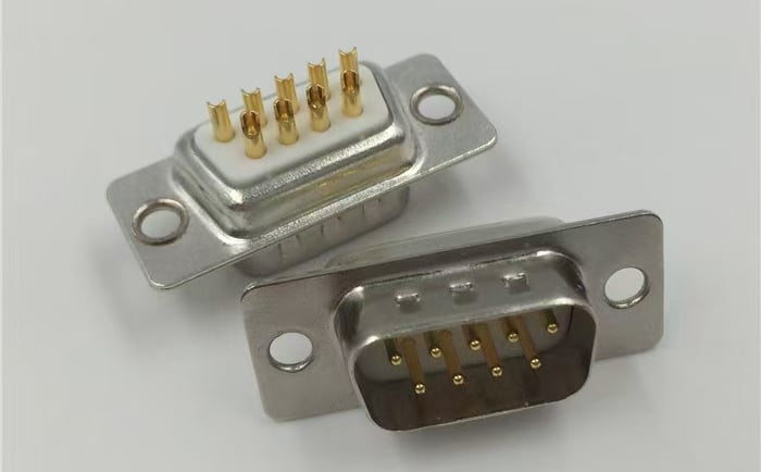
High mating life (>1000 cycles) → Turned contact
High-volume, cost-sensitive → Stamped contact
Special plating: Gold plating (signal/low contact resistance), Tin plating (soldering), Silver plating (high current)
Step 6: Accessories and secondary processing
Is injection molding of cable assemblies required? Is overmolding required?
Are locking screws (4-40, M2.5, M3) required? Are dust covers required?